top of page

1. 1st an initial alignment is created & the part is inspected per print / GD&T.
2. A nominal and actual local coordinate system are created on the CAD & Scan.
3. Discrete inspection points are created on the manufacturing datums.
4. A subsequent RPS / Best Fit alignment is created on the critical features (to optimize dev)
5. A transformation matrix is extracted between the nominal and actual local coordinate system, along with the discrete inspection points.
6. This 'shift' can then be fed back into the manufacturing process so subsequent parts are made within tolerance. (toolpath and or fixture adjustment)
ADAPTIVE MANUFACTURING
- FEATURE OPTIMIZATION BY DATUM SHIFT -
By using the tools within GOM Inspect professional, we can create a transformation matrix that can be be used to adjust the physical part within a machining center to optimize a surface, or set of features such as a hole pattern.

This video has been deleted.
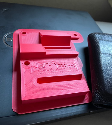
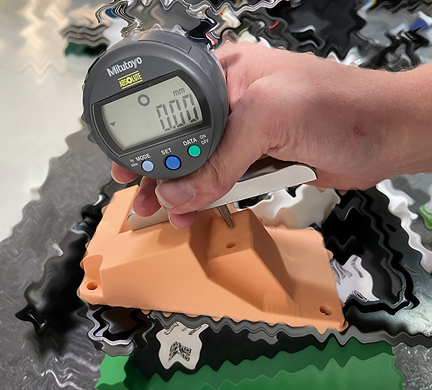
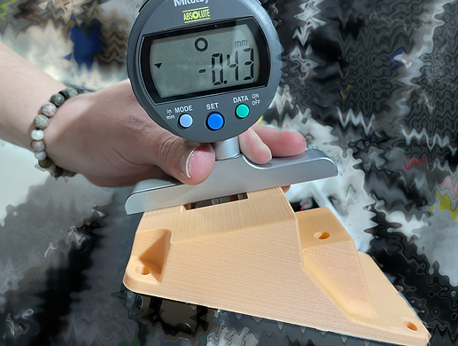
3D Printed Inspection Fixture
Go / No-Go & Depth Mic Version
Created with Fusion 360
Printed with Ultimaker II
Validated via CMM & Gage R&R

qc Above
atos
3d-Scanner
Proficient
with
GD&T
qc below
tri-top
photogrammetry
bottom of page